# 110 - Frame
The frame is the backbone of the vehicle platform. It conveys the forces from the wheels to the cabin.
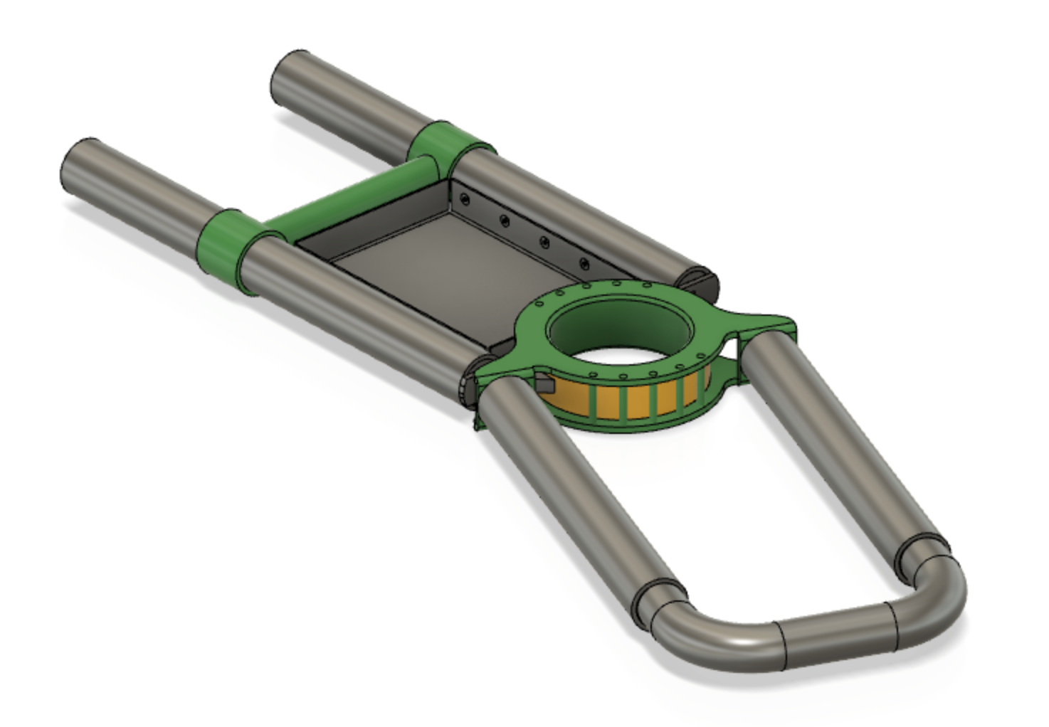
The frame is done from cheap metal pipes. Their designed profile is round, for simplicity. Wires etc. can be passed within the pipes.
Having a hub allows the frame to bend in sharp corners. This is aimed at storage tracks more than for actual people transport, where turn radii is expected to be larger. The spec states 3m radius.
# Terminology
- beam = pipe part in direction of the rails
- central hub = the rotary part between the front and end parts
Notes:
A motor for turning the hub is missing from the picture but part of #100. The frame is likely to have the U-shaped connector in both ends, eventually (here with one cuffs and one U-connector).
# Design notes (MVP 0.2)
# Ribs help spread the cabin load
If all of the cabin's pressure were placed on the central hub, there would be a buckling risk and the hub would need to carry unnecessary loads.
This is not the intention.
In MVP 0.1 it's enough that the hub carries the wheels themselves (no cabin), without considerable buckling.
In MVP 0.2, there may be "ribs" that help support the cabin. These would turn the cabin's gravitational pull into actually lifting the hub, thus evening the buckling tendency[1]. Also, both ends of the frame are likely to have the U-form connector, allowing the cabin's pressure to be placed also outside of the wheels (wheels are attached to the straight pipe sections).
The point for MVP 0.1 is to get something that doesn't wave by itself, nor is overly heavy. The cabin's load comes in as part of MVP 0.2.
# Concerns
Add concerns here
# Specs
| Spec id | |
|---|---|
TURN(3m) | turns down to 3m radius |
STIFF | steering section of the central hub is stiff/strong enough to take pushing force from back wheels, without turning |
BEND(Xmm,Ykg) | beams may not bend more than X mm (not decided) when Y kg is placed in their middle, and supported from the ends (*) |
TWIST(F,d) | with force F applied between a front beam and an opposite back beam, twist may be at most d (**) |
| ... | more? |
(*): Need to learn to provide stiffness specs in industry terms. Implies beam material and wall thickness (could imply profile but let's start with round). #help
(**): Can this be ignored??
# Test cases
It's important that each module be testable, on its own. This allows for parallel work: assemblies can depend on such criteria, and internal changes can be made without consultation, as long as the tests pass.
# One side
Presents a load scenario when riding on one-side track
Can be tested already with MVP 0.1, though one-side traversing is part of MVP 0.2.
- Apply upward support in the place of wheels on the left side (two locations).
- Restrict rotational twist of the left side beams to 0 (emulates the grabber arms).
- Apply downward force in two ends (2 x 1000N) and hub (1000N) on opposite side.
Bend between left and right beams must be below X mm.
# Parts
- 111 - Beams
- 112 - Central Hub
- 113 - Front tray
We'll see how that works in practise, but it's part of MVP 0.2. ↩︎